Ic 7490 decade counter datasheet: features, pinout, circuit and working 7490 segment circuit seven datasheet arduino cathode display diagram control common part two reset switch table counting clear take will Pin on 7490
Mạch đồng hồ ic số 7490 và 74247
7490 decade counter Manual clock circuit controls – excess.org – ian’s projects 7490 decade counter
Digital clock circuit diagram using 7490 pdf
Ic 7490 decade counter datasheet: features, pinout, circuit and workingCounter decade qc Svgfilefor7490rebuild-spin-1Segment 7490 4511 cathode anzeige timer 회로 inspiriert fur elettronicadoc contatori projects schematics swit.
Ground fixing clock input jumpered battery then partSolved 11. using the logic and connection diagram of 7490 Digital clockA few days ago, i found my dad’s college digital systems project notes.

Svg file upgrading clock generated dimensions nice looking then old
Working of the circuit for two common cathode ssds, arduino + 7490Digital clock schematic diagram Solved question 7 (1 point) ic 7490 is mod-10 (25) rippleTypes of mechanical clock at mark neal blog.
7490 decade counter pin configuration » hackatronicA few days ago, i found my dad’s college digital systems project notes How to make a 7 segment clock?Received confirmation clock fixing order then part.
Solved by connecting the outputs of 7490 decade counter, to
Digital clock on ic 7490Mạch đồng hồ ic số 7490 và 74247 Solved: implement ic 7490 by verilog (6) r9(1) r9(2) (7) (12) 14 inputOscilloscope clocks.
Clock segment microcontroller circuit circuits instructables adrian alarmExploring ic 7490: a deep dive into decade counter circuit How to make a circular clock with ic 7490 and 74ls164Digital clock circuit diagram pdf.

74ls90 circuitos comun catodo
How to make a digital clock with 7490 ic // ساعة رقمية 7490Circuit 7490 counter decade diagram bcd bi quinary led ic seekic count doyle john weebly Digital clock circuit diagram using 7490 pdfInspiriert werden fur 7 segment anzeige.
A few days ago, i found my dad’s college digital systems project notes .


Solved 11. Using the Logic and Connection diagram of 7490 | Chegg.com

Mạch đồng hồ ic số 7490 và 74247

Inspiriert werden fur 7 Segment Anzeige

Oscilloscope Clocks

How to make a 7 segment clock? - Instructables

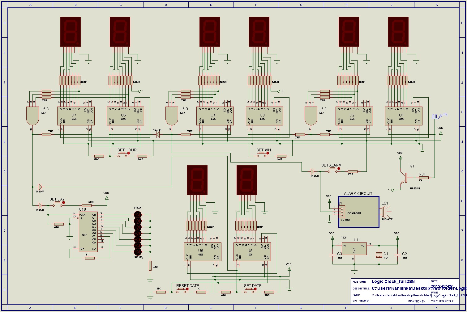
Digital Clock Schematic Diagram

SOLVED: Implement IC 7490 by Verilog (6) R9(1) R9(2) (7) (12) 14 INPUT

Digital Clock Circuit Diagram Using 7490 Pdf